
C++, OpenGL and more...
 Megabyte Softworks Facebook
 Megabyte Softworks Patreon
Hello guys! Welcome to my 22nd tutorial of my OpenGL4 series! In this one, we will find out how can we generate two more primitives - cylinder and sphere. This will make our primitives set richer and also those objects are very nice to demonstrate some effects. So take a rest, stay a while and read through the article  .
.
First we will start of with a cylinder. This one is a bit easier and is a good start, before we move to the more complex sphere. Cylinder consists of N slices (N can be defined of course). The more slices we have, the smoother geometry will be generated. To understand what I mean with slices, following picture should help:
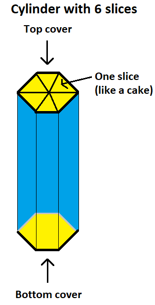
If you would think of a cylinder as of a cake, now we made 6 slices out of the full cake . Let's think a second now to come up with a good solution how to render such an object. First thing to realize is, that the walls of cylinder (painted with blue) are independent of the top and bottom cover (painted with yellow). This observation is quite important - we need to generate separate set of vertices for walls and covers (the vertices can't be shared of different texture coordinates and normals). I have decided not to use indexed rendering here, as it would be a waste (every vertex is a unique one and with indexing we would waste memory).
Rendering walls is pretty straightforward. We can render it with a triangle strip, alternating the top and bottom vertices like this:
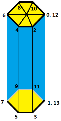
I hope it's pretty clear here what we're doing - we just take top vertex / bottom vertex, top vertex / bottom vertex etc. The one thing worth noting is, that vertices 0, 12 and 1, 13 are same, but because we don't use indexed rendering, we simply duplicate them in memory (to avoid duplication, we would have to go with indexed rendering, but indices would take much more memory than two duplicated vertices  ). Let's have a look at the code, that generates vertices of the walls:
void Cylinder::initializeData()
{
    // ...

    // Pre-calculate sines / cosines for given number of slices
    const auto sliceAngleStep = 2.0f * glm::pi() / float(_numSlices);
    auto currentSliceAngle = 0.0f;
    std::vector sines, cosines;
    for (auto i = 0; i <= _numSlices; i++)
    {
        sines.push_back(sin(currentSliceAngle));
        cosines.push_back(cos(currentSliceAngle));

        // Update slice angle
        currentSliceAngle += sliceAngleStep;
    }

    if (hasPositions())
    {
        // Pre-calculate X and Z coordinates
        std::vector x;
        std::vector z;
        for (auto i = 0; i <= _numSlices; i++)
        {
            x.push_back(cosines[i] * _radius);
            z.push_back(sines[i] * _radius);
        }

        // Add cylinder side vertices
        for (auto i = 0; i <= _numSlices; i++)
        {
            const auto topPosition = glm::vec3(x[i], _height / 2.0f, z[i]);
            const auto bottomPosition = glm::vec3(x[i], -_height / 2.0f, z[i]);
            _vbo.addRawData(&topPosition, sizeof(glm::vec3));
            _vbo.addRawData(&bottomPosition, sizeof(glm::vec3));
        }

        // ...
    }
}
First, we pre-calculate sines and cosines for every slice - they will be re-used both for vertex and normal calculations. Then, as stated above, we add sequentially top / bottom vertex of each cylinder slice. It's that simple! Regarding texture coordinates, I have decided to map texture twice around the cylinder - it looks good . Texture mapping is simply linear and there is really no complex logic involved, so just have a look at it yourself (GitHub repo link). Finally, normals are even easier - they are just sines and cosines of slices, that we pre-calculated before (GitHub repo link).
Top and bottom covers have to be treated separately. In this case, we can use a different rendering method called triangle fan. Let's have a look at the vertex progression for covers:
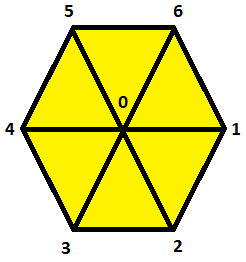
You can see here, that we start in the middle of the cover and then go around the perimeter, like a fan (thus the name triangle fan). Texture coordinates for covers are simple again - we can just take pre-calculated sines and cosines to generate a circle from texture coordinates (GitHub repo link). Normals are even easier - for top cover, normal is always glm::vec3(0.0, 1.0, 0.0) (pointing up) and glm::vec3(0.0, -1.0, 0.0) (pointing down).
Finally let's have a look at cylinder rendering code:
void Cylinder::render() const
{
    if (!_isInitialized) {
        return;
    }

    glBindVertexArray(_vao);

    // Render cylinder side first
    glDrawArrays(GL_TRIANGLE_STRIP, 0, _numVerticesSide);

    // Render top cover
    glDrawArrays(GL_TRIANGLE_FAN, _numVerticesSide, _numVerticesTopBottom);

    // Render bottom cover
    glDrawArrays(GL_TRIANGLE_FAN, _numVerticesSide + _numVerticesTopBottom, _numVerticesTopBottom);
}
Pretty short and simple right? We just bind our VAO, where the generated vertices are and then we render cylinder walls with GL_TRIANGLE_STRIP and top cover and bottom cover with GL_TRIANGLE_FAN.
And I guess that's it for the cylinder! It's not that complex of an object in the end and now we can move on to the real challenge - sphere  .
.
Sphere is a really cool object. I mean it's perfectly round, mathematically spoken it has an easy equation and you can demonstrate all kinds of effects on it! And that's why we have to learn, how such a sphere can be generated. First of all, what does surface of a sphere consist of? It's just all points in the space, that have the distance r from the sphere center. For sphere with a center at [x0, y0, z0], the following equation holds true:
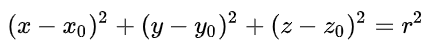
That is, every point [x, y, z], that holds true for this equation is a point on the sphere! Ok, that was a bit of a theory, let's convert this to a real deal . In order to generate sphere mesh, we will again have to select first, how many subdivision do we want, or simply how smooth the mesh will be. This time, it's going to be not only slices (same principle as cylinder), but also stacks - this means, if you take one slice of your sphere cake, how many times is it subdivided in the vertical direction. A picture will help here definitely :
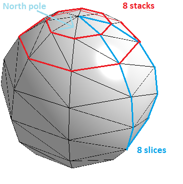
In the picture above, there are 8 slices and 8 stacks. In order to render a sphere, we will render it in a following way - we go stack by stack and within each stack, we render desired number of slices. But watch out! If you look closely at the picture, you can see that the first (and last stack) are rendered in a somewhat different way. We can call the first stack a north pole and the last stack a south pole. Both poles are rendered in a very similar way as cylinder covers, but this time with triangles, not triangle fan (you will see why a bit later). Then, the other non-pole stacks are rendered using a triangle strip, same as in cylinder case!
I hope I've made myself clear and now if you understand how this works, we can restrict the minimal number of slices and stacks. It should not have less than 3 slices (otherwise sphere would be a flat roundy thing ) and it should also not have less than 2 stacks (we really need at least north and south pole, otherwise it really does not make much sense to render it). If you want, you can change the code to allow this and then see for yourself .
Let's move onto a sphere mesh generation. To simplify things, we will generate vertices for every stack and within each stack for every slice. Even if the pole center vertices will be duplicated, it's not an issue. In this case, it's very effective to go for an indexed rendering - vertices between stacks are shared, so better to duplicate indices than to duplicate whole vertices. Let's examine how the vertices positions are generated:
void Sphere::initializeData()
{
    // ...

    // Pre-calculate sines / cosines for given number of stacks
    const auto stackAngleStep = -glm::pi() / float(_numStacks);
    auto currentStackAngle = glm::pi() / 2.0f;
    std::vector stackSines, stackCosines;
    for (auto i = 0; i <= _numStacks; i++)
    {
        stackSines.push_back(sin(currentStackAngle));
        stackCosines.push_back(cos(currentStackAngle));

        // Update stack angle
        currentStackAngle += stackAngleStep;
    }

    // Generate sphere vertex positions
	if (hasPositions())
	{
        for (auto i = 0; i <= _numStacks; i++)
        {
            for (auto j = 0; j <= _numSlices; j++)
            {
                const auto x = _radius * stackCosines[i] * sliceCosines[j];
                const auto y = _radius * stackSines[i];
                const auto z = _radius * stackCosines[i] * sliceSines[j];
                _vbo.addData(glm::vec3(x, y, z));
            }
        }
	}

    // ...
}
First, we precalculate sine and cosine values (same case as cylinder), they will come handy by normals generation. Afterwards, the position of a point on a sphere is calculated as a combination of sines and cosines together with radius. As mentioned before, the first stack will generate a point in the same position (north pole center) and last stack the same (south pole center). But that's ok and why? Because those points will have different texture coordinates! The position and normal might be same over and over again, but texture coordinates will differ. And how to generate them? I have chosen a simple linear mapping around the sphere:
void Sphere::initializeData()
{
    // ...

  	if (hasTextureCoordinates())
	{
        for (auto i = 0; i <= _numStacks; i++)
        {
            for (auto j = 0; j <= _numSlices; j++)
            {
                float u = 1.0f - float(j) / _numSlices;
                float v = 1.0f - float(i) / _numStacks;
                _vbo.addData(glm::vec2(u, v));
            }
        }
	}

    // ...
}
That is not the only possibility though. I have also added multiple ways how one can generate texture coordinates of a sphere, but I found this one simplest and also the best. You can check out the other options here in this GitHub repo link. The only problem with linear mapping is that there are some mapping artifacts at the poles. I don't really konw why, I tried to get rid of them but somehow I could not, so if anyone gives me an idea what I do wrong, I will be glad .
Generating normals is again a matter of re-using precalculated sine and cosine values:
void Sphere::initializeData()
{
    // ...

	if (hasNormals())
	{
        for (auto i = 0; i <= _numStacks; i++)
        {
            for (int j = 0; j <= _numSlices; j++)
            {
                const auto x = stackCosines[i] * sliceCosines[j];
                const auto y = stackSines[i];
                const auto z = stackCosines[i] * sliceSines[j];
                _vbo.addData(glm::vec3(x, y, z));
            }
        }
	}

    // ...
}
And finally, we need to generate indices for indexed rendering. Basically we just make out triangles of the pole stacks and then triangle strips of the middle stacks:
void Sphere::initializeData()
{
    // ...

    // Now that we have all vertex data, generate indices for north pole (triangles)
    for (int i = 0; i < _numSlices; i++)
    {
        GLuint sliceIndex = i;
        GLuint nextSliceIndex = sliceIndex + _numSlices + 1;
        _indicesVBO.addData(static_cast(sliceIndex));
        _indicesVBO.addData(static_cast(nextSliceIndex));
        _indicesVBO.addData(static_cast(nextSliceIndex+1));
    }

    // Then for body (triangle strip)
    GLuint currentVertexIndex = _numSlices + 1;
    for (int i = 0; i < numBodyStacks; i++)
    {
        // Primitive restart triangle strip from second body stack on
        if (i > 0)
        {
            _indicesVBO.addData(_primitiveRestartIndex);
        }

        for (int j = 0; j <= _numSlices; j++)
        {
            GLuint sliceIndex = currentVertexIndex + j;
            GLuint nextSliceIndex = currentVertexIndex + _numSlices + 1 + j;
            _indicesVBO.addData(sliceIndex);
            _indicesVBO.addData(nextSliceIndex);
        }

        currentVertexIndex += _numSlices+1;
    }

    // And finally south pole (triangles again)
    GLuint beforeLastStackIndexOffset = _numVertices - 2*(_numSlices + 1);
    for (int i = 0; i < _numSlices; i++)
    {
        GLuint sliceIndex = beforeLastStackIndexOffset + i;
        GLuint nextSliceIndex = sliceIndex + _numSlices + 1;
        _indicesVBO.addData(static_cast(sliceIndex));
        _indicesVBO.addData(static_cast(sliceIndex + 1));
        _indicesVBO.addData(static_cast(nextSliceIndex));
    }

    // ...
}
Now that our buffers are ready and filled with data, rendering is just a matter of few simple calls :
void Sphere::render() const
{
	if (!_isInitialized) {
		return;
	}

	glBindVertexArray(_vao);

    glEnable(GL_PRIMITIVE_RESTART);
    glPrimitiveRestartIndex(_primitiveRestartIndex);

    // Render north pole
    glDrawElements(GL_TRIANGLES, _numPoleIndices, GL_UNSIGNED_INT, (void*)(sizeof(GLuint)*_northPoleIndexOffset));

    // Render body
    glDrawElements(GL_TRIANGLE_STRIP, _numBodyIndices, GL_UNSIGNED_INT, (void*)(sizeof(GLuint)*_bodyIndexOffset));

    // Render south pole
    glDrawElements(GL_TRIANGLES, _numPoleIndices, GL_UNSIGNED_INT, (void*)(sizeof(GLuint)*_southPoleIndexOffset));

    // Disable primitive restart, we won't need it now
    glDisable(GL_PRIMITIVE_RESTART);
}
And that's basically it! Of course, there are many small implementation details here and there, I just can't go through every single line of code. But if you got the main idea, you should be able to figure out everything to the last detail .
Because I wanted to demonstrate the spheres and cylinders in some fashionable way, I have decided to implement a solar system . Basically every planet (and the Sun) are spheres and then there is a strange object that is a space station. I have created dedicated classes for the planet and the space station. This is how the tutorial looks:
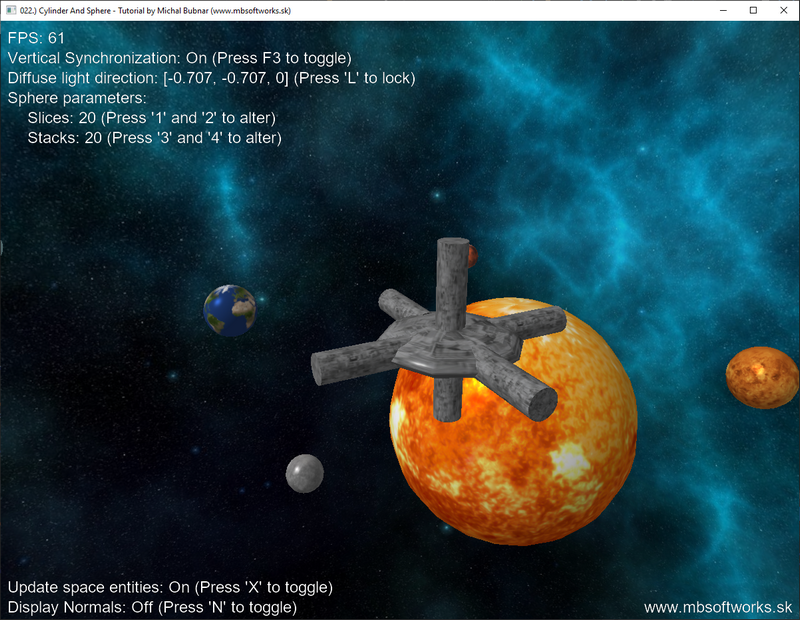
I even searched Wikipedia for the real figures of how long does it take the planets to orbit around the Sun, so it should be more or less correct . I have also gave you controls to play with number of slices / stacks of a spheres to see how it changes the mes smoothness. Don't forget to display normals as well, it looks kinda cool .
I really hope that you've enjoyed my pretty long and complex tutorial and that you've learned something today. The generating of a sphere mesh is not that difficult after all. To some extent, it's similar to a cylinder mesh generation with a few twists here and there. In case of any questions, write me to a discussion below or on my Facebook or drop me an e-mail .
 Download 7.44 MB (1161 downloads)