
C++, OpenGL and more...
 Megabyte Softworks Facebook
 Megabyte Softworks Patreon
Hello friends! I'm really glad that you stumbled upon my 26th tutorial of my OpenGL 4 series, where you can learn about the orbit camera! In comparison with previous tutorial about transform feedback particle system, this tutorial is going to be a lot easier and much more relaxing  . Just keep reading and you will see, that it's really a piece of cake
  .
.
Orbit camera (also known as arcball camera) is a simple type of camera, that orbits around the object (like a planet) along a sphere. The simplicity of this camera is, that the view point is always the center of the sphere and the eye is just floating around the sphere. In order to move around the sphere, we have to understand the spherical coordinates. And for easier understanding, let's start with simpler 2D version - polar coordinates.
In 2D, we can represent a position in space with [x, y] coordinates. That's simple, but there is an alternative way how to represent position in space as well - with radius and angle. If you imagine the whole space as an infinitely big circle, then you can represent all positions as well! Look at the picture:
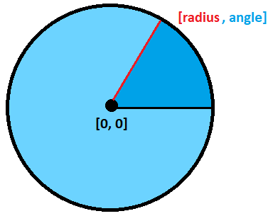
That means basically, that to reach our position, we first turn around by the specified angle and then travel the radius distance! I think the concept is really not that difficult to grasp. I also have a feeling that now you start to guess, what are spherical coordinates. Yes, it's just natural extension of this to 3D space  .
.
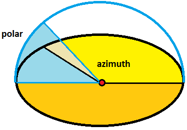
Now that we are in 3D, we can again define a position apart from [x, y, z] coordinates in a similar fashion as with polar coordinates, but this time, we will need two angles instead of one - azimuth angle and polar angle. The azimuth angle is the rotation angle around Y axis, so with azimuth we control looking to the left and right, polar angle is for looking up and down . Have a look at the picture again:
But why exactly do we need those coordinates? Because that's how we can implement the orbit camera easily! All we need to do is to control those three parameters - radius (which is also a zoom level), azimuth angle and finally the polar angle! Having all three parameters, all that remains is to calculate the real [x, y, z] position and that's it - we have the eye position of the camera! Remember, the view point is always center of the sphere, so all we need is to calculate the eye of the camera, that orbits around the sphere .
So the real question is - how can we convert from polar coordinates to standard 3D coordinates? I didn't come up with it, it's just everywhere to be found on the internet. But converted to my namings and angles, here is the equation:
Given sphere with center point c and [a, p, r], where:
Now that we know the whole theory, let's have a look at the code .
Below is the overview of the whole OrbitCamera class:
class OrbitCamera
{
public:
	OrbitCamera(const glm::vec3& center, const glm::vec3& upVector, float radius, float minRadius, float azimuthAngle, float polarAngle);

    void rotateAzimuth(const float radians);
    void rotatePolar(const float radians);
	void zoom(const float by);

	void moveHorizontal(const float distance);
	void moveVertical(const float distance);

    glm::mat4 getViewMatrix() const;
    glm::vec3 getEye() const;
    glm::vec3 getViewPoint() const;
    glm::vec3 getUpVector() const;
    glm::vec3 getNormalizedViewVector() const;
    float getAzimuthAngle() const;
    float getPolarAngle() const;
    float getRadius() const;

private:
    glm::vec3 center_; // Center of the orbit camera sphere (the point upon which the camera looks)
    glm::vec3 upVector_; // Up vector of the camera
    float radius_; // Radius of the orbit camera sphere
    float _minRadius; // Minimal radius of the orbit camera sphere (cannot fall below this value)
    float azimuthAngle_; // Azimuth angle on the orbit camera sphere
    float polarAngle_; // Polar angle on the orbit camera sphere
};
I really think that the namings of methods / variables should be mostly self-explanatory. Nevertheless, let's analyze few core functions .
void OrbitCamera::rotateAzimuth(const float radians)
{
    azimuthAngle_ += radians;

    // Keep azimuth angle within range <0..2PI) - it's not necessary, just to have it nicely output
    const auto fullCircle = 2.0f*glm::pi();
    azimuthAngle_ = fmodf(azimuthAngle_, fullCircle);
    if (azimuthAngle_ < 0.0f) {
        azimuthAngle_ = fullCircle + azimuthAngle_;
    }
}
Here we rotate azimuth angle. The angle is free to go in a full circle, the only extra thing I do here is keeping the angle within the range 0 ... 2PI. This is done by function fmod. It's like a standard integer mod, but for floats. Should we go below 0.0f, then the fmod returns negative value, that's why we need to add it to the full circle .
And why exactly do I keep the angle in this range? One reason is a nice output of angle in the HUD (it's easier to imagine 0 ... 360 degrees than 53531 degrees ), another is, that if we would rotate many many times around and the float value would go very high (or very low), we would start losing precision, which could lead to unexpected results. Question is who would be patient enough to rotate so much that he bumps into floating point precision problems .
void OrbitCamera::rotatePolar(const float radians)
{
    polarAngle_ += radians;

    // Check if the angle hasn't exceeded quarter of a circle to prevent flip, add a bit of epsilon like 0.001 radians
    const auto polarCap = glm::pi() / 2.0f - 0.001f;
    if (polarAngle_ > polarCap) {
        polarAngle_ = polarCap;
    }

    if (polarAngle_ < -polarCap) {
        polarAngle_ = -polarCap;
    }
}
Here we rotate polar angle. However, we restrict this angle to go up to quarter of a circle (PI / 2). But why you may ask? Because if we don't do that, the camera will flip around when you exceed the quarter circle (see it for yourself by commenting those conditions out). The main problem here is, that after exceeding this, you are not looking like forward anymore, your're looking backward from now on. I haven't figured out yet, how to make a perfect camera (like one in Blender software), but I surely will research this and write a tutorial later .
Why is there a bit of epsilon? Because this way we won't reach full quarter of circle. If we do, then up vector and view vector would become collinear and I suppose it would not work properly anymore.
void OrbitCamera::zoom(const float by)
{
    radius_ -= by;
    if (radius_ < _minRadius) {
        radius_ = _minRadius;
    }
}
This is pretty easy - we're just manipulating the radius. If the radius falls below the minimal radius, we just cap it .
glm::vec3 OrbitCamera::getEye() const
{
    // Calculate sines / cosines of angles
    const auto sineAzimuth = sin(azimuthAngle_);
    const auto cosineAzimuth = cos(azimuthAngle_);
    const auto sinePolar = sin(polarAngle_);
    const auto cosinePolar = cos(polarAngle_);

    // Calculate eye position out of them
    const auto x = center_.x + radius_ * cosinePolar * cosineAzimuth;
    const auto y = center_.y + radius_ * sinePolar;
    const auto z = center_.z + radius_ * cosinePolar * sineAzimuth;

    return glm::vec3(x, y, z);
}
This one is really important, because it's the core code of the orbit camera. Here, the azimuth angle, polar angle and radius get translated into the position using the equation stated above. This code is simply implementation of the equation .
void OrbitCamera::moveHorizontal(const float distance)
{
    const auto position = getEye();
    const glm::vec3 viewVector = getNormalizedViewVector();
    const glm::vec3 strafeVector = glm::normalize(glm::cross(viewVector, upVector_));
    center_ += strafeVector * distance;
}

void OrbitCamera::moveVertical(const float distance)
{
    center_ += upVector_ * distance;
}
With those functions we can move the camera around (moving the center of orbit camera sphere). Moving horizontally utilizes same logic for strafing as in the 006.) Camera Pt.2 - Flying Camera and moving vertically is simply sliding along up vector .
Rest of the functions are not really worth explaining, they are just getters with little to no logic .
In this tutorial, you can turn the wireframe mode on / off with the 'X' button. How to implement this on OpenGL? It's really simple - you just have to call one OpenGL method prior to the rendering. In order to render wireframe, call following method:
glPolygonMode(GL_FRONT_AND_BACK, GL_LINE);And to restore normal rendering mode, call following method:
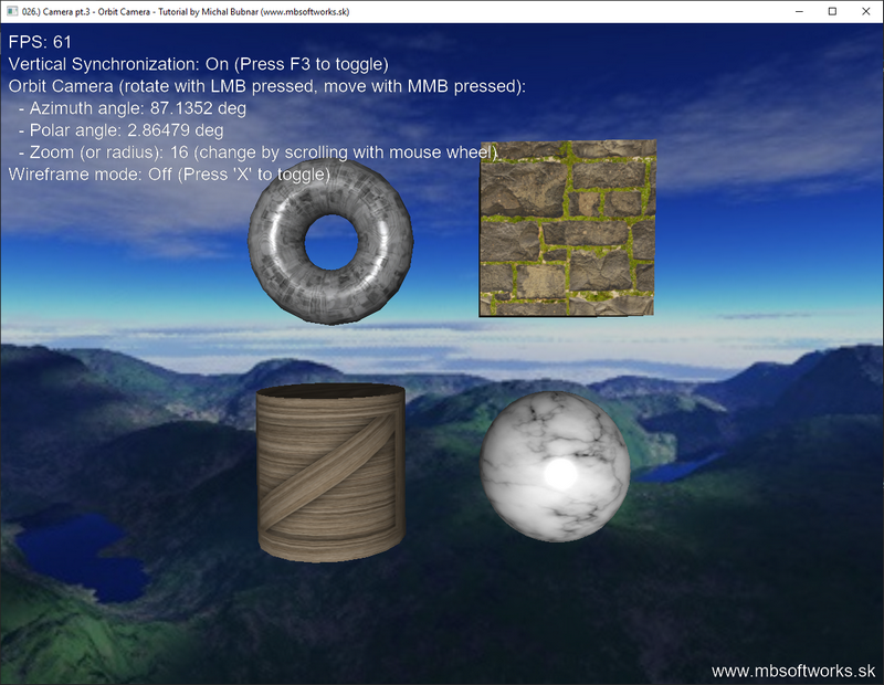
glPolygonMode(GL_FRONT_AND_BACK, GL_FILL);The result is following scene showing 4 primitives - torus, cube, cylinder and sphere, which you can observe with our orbit camera (use mouse to control it - LMB to rotate, MMB to move around):
So as you see - today we've achieved something very nice and in the end it was not that difficult . I think it's a really nice addition to our arsenal of cameras, we now have 3 already! I think there will once be last camera tutorial, that allows you to rotate freely in every direction, something like a space flight simulator .
 Download 3.71 MB (1145 downloads)